Device, Cable, and Panel Labeling scheme.
----
This is constantly changing as I try to document and standardize what I do in my installations.
Hardware and Labels used:
Printer: Brady M710 Label Maker:
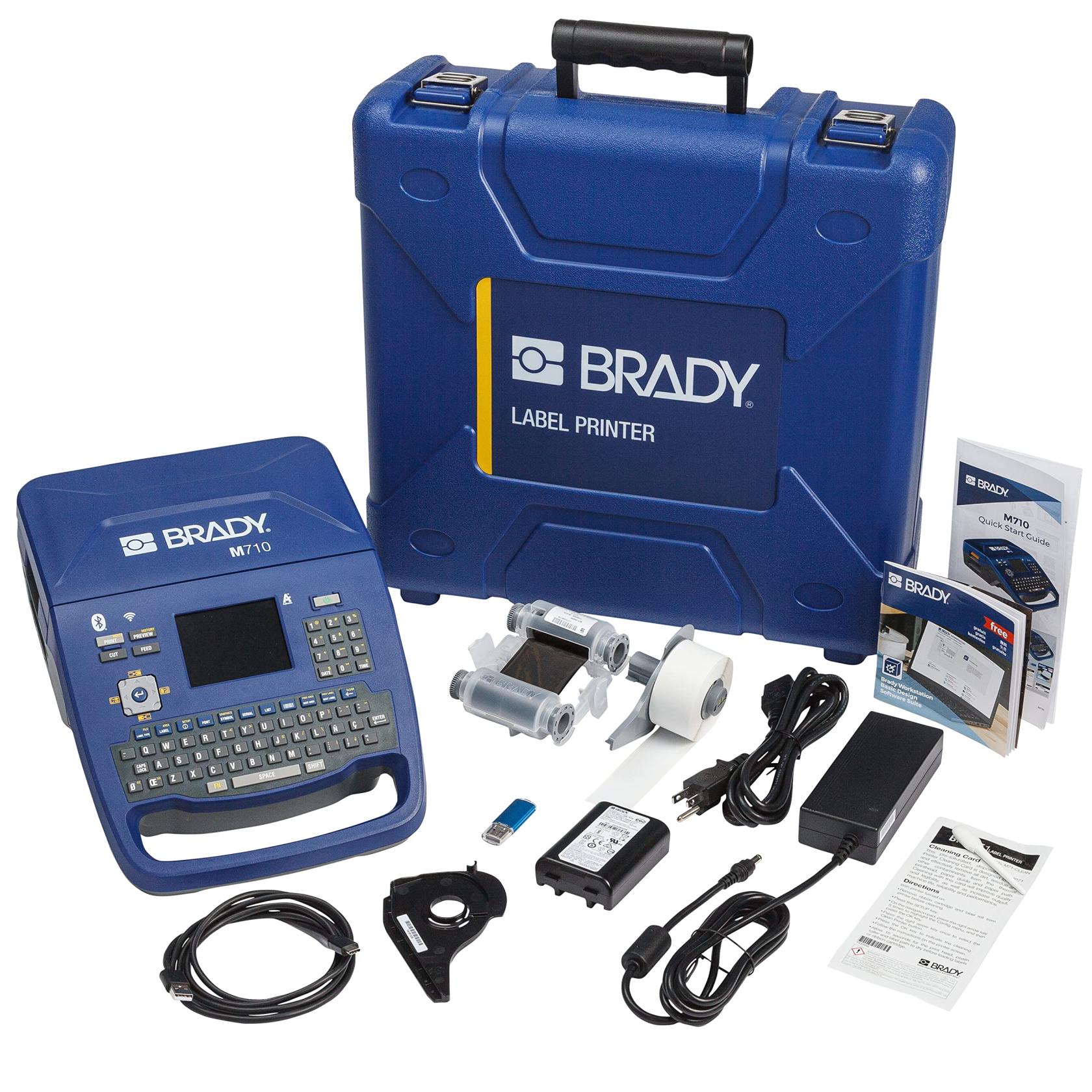
Labels:
| Label Type | Label Size | Brady Part Numer [URL] | Count Per Roll | Estimate Price | Required Ribbon |
| Basic Sticker | 1.0" x 1.0" | M7-19-423 | 250 | $43.50 | |
| Metallic Label | 1.0" x 2.0" | 100 | $40.00 | ||
| Cable Wrap Sticker | 1.5" x 1.0" | 250 | $68.00 | R4300 - $73.00 |
Printable Site Template Guide:
Editable Document: NetworkIdentification.docx
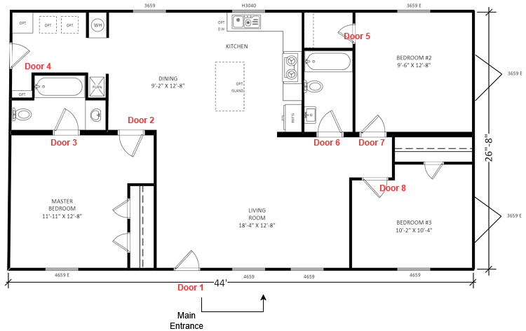
Panels / Doors Labels:
All panels are counted clockwise from either MPOE or Main Entry.
Start at the Main Doorway and count clockwise around the Facility.
| Location/Type | First | Example | Expansion |
| Main Point of Entry | (Site)-MPOE.(Floor).(door) | SASC-MPO.1.6 | N/A - Only 1 MPOE per side |
| Intermediate Distribution Frame | (Site)-IDF.(Floor).(Door) | SASC-IDF.1.1 | IDF-1-1a, IDF-1-1b |
| Media Cabinets/Panels | (Site)-PNL.(Floor).(Panel Number) | SASC-PNL.1.1, SASC-PNL.2.1 | |
| Facility Doors: | (Site)-FL-DR## |
SASC-01-DR01 |
Notes:
MPOE - This is where the internet comes into the building. In residential buildings, it is commonly seen as a utility hidden under stairs or in basements. In large commercial buildings, it's widely known that risers [cables that link IDFs in other floors or wings] are used.
IDF - This is where your switching or server equipment is located to support each floor. This commonly hosts switches that connect back to the MPOE
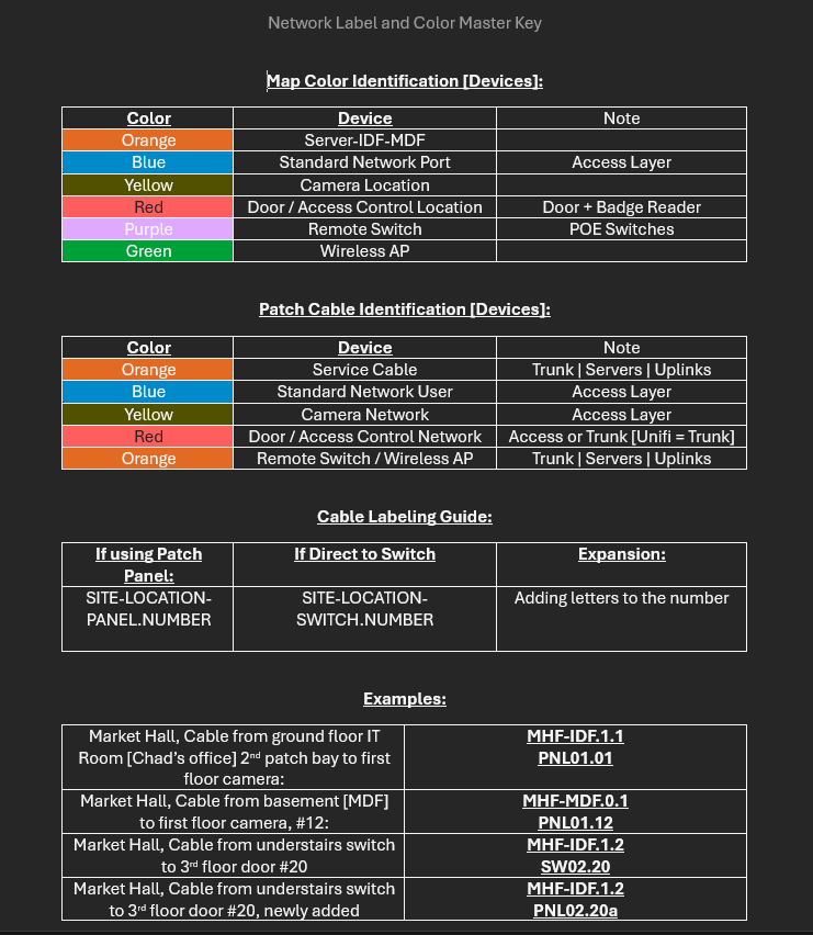
Cable Labels:
606-B Notes:
Near end = AG09-35:01/AJ06-35:01
Far end = AJ06-35:01/AG09-35:01
If standing at rack location AG09, reading this near-end cable identifier will describe both the near-end and far-end locations.
AG09 = Rack or cabinet at grid location AG09 within the data center
-35 = Patch panel located 35 rack units from the bottom in rack AG09
:01 = Port 01 in patch panel located 35 rack units from the bottom of rack AG09
/ = Separator for near-end/far-end location description
AJ06 = Rack or cabinet at grid location AJ06 within the data center
-35 = Patch panel located 35 rack units from the bottom in rack AJ06
:01 = Port 01 in patch panel located 35 rack units from the bottom of the rack in AJ06
| Examples | First | Example | Expansion |
| SASC Patch Bay to Environment | (Panel Number).(Port Number on Panel) | P6.12 | P6.12a | P6.12b [only applies to split cables] |
| SASC to Device | (Panel Number).(Port Number on Panel) | P6.12 | P6.12a | P6.12b [only applies to split cables] |
| Wilson-MHF | (site)-(IDF#)-(Panel Number).Port Number | MHF-IDF2.1-P1.1 | N/A |
Device Labels:
Controllers: Physical hardware in Panels, Walls or mounted to walls
| Location/Type | First | Example | Expansion |
| Door Access Hub | (site)-CTL.(floor)-(door number) | SASC-CTL.1.05 | SASC-CTL.1.05a |
| Door Intercom | (Acesss Hub)-IntCom | SASC-CTL.1.05-IntCom | IntCom |
| Door Badge Reader | (Acesss Hub)-Reader | SASC-CTL.1.05-Reader |
Network Devices:
| Location/Type | First | Example | Expansion |
| Firewall/Router | (site)-FW## | 925-FW01 | 925-FW02 |
| Switches | (site)-SW## | 925-SW01 | 925-SW02 |
| Cameras | (location)-(object-in-camera) | INTERNAL-CashReg | INTERNAL-CashReg02 |
Notes:
Cameras have special naming schemes. We define them as internal or external to quickly identify access. Tenants and Employees typically can access external cameras, but internal camera access is heavily policed. A camera overlooking a driveway would be called "EXTERNAL-Driveway-North"
Patch Bay printed label templates:
PatchBaySize_12portLevitonKeystone.docx
PatchBaySize_12portSurfacemount.docx
PatchBaySize_24portKeystone.docx
PatchBaySize_48port.docx
PatchBaySize_24port.docx
Wire In between Devices:
2x Layer labels. Order of spanning tree. Top of label = First location. The bottom of the Label = end of the cable.
| Device | Fire | Example | Expansion/Options |
| Device |
Top: Where it terminates Bottom: What it terminates |
|
|
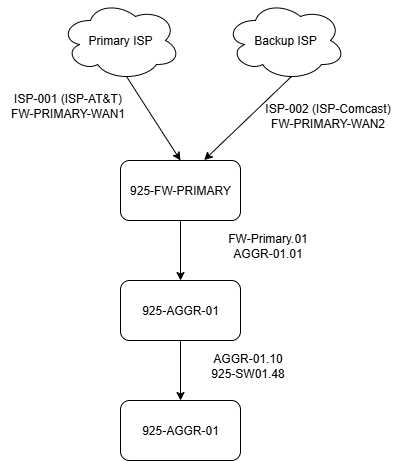
| ISP to Firewall/Router |
(site)-ISP.## [Number or name] FW-Primary-PORT |
MHF-ISP.001 FW-Primary-WAN1 |
ISP-AT&T FW-Secondary-WAN2 |
| Router to Distribution Switch |
FW/ROUT.Port AGGR-##.PORT |
FW-Primary.03 AGGR-01.01 |
FW-Secondary.03 AGGR-02.01 |
| Router/Agg to L3/2 Switch IN MPOE |
AGG-##.Port SW##.Port |
AGGR-01.10 SW01.49 |
AGGR-02.12-BONDa AGGR-02.13-BONDb |
| Patch Cables between IDF/MPOE and the environment |
(thing)-(floor)-(number) Service*-### *NET | *TEL | *COM | |
MHF-IDF.1.2 NET-001 *TEL-001 |
IDF-1-2 NET-001a |
|
Riser Cables [between MPOE, IDF, Panels] |
(site)-(thing).(floor).(number) (site)-(thing).(floor).(number) |
MHF-IDF.1.001 SASC-PNL.2.001 |
IDF-1-1.001a, IDF-1-1.001b PNL-1-2.002a |
| Badge Readers |
(site)-CTL.(floor).(number)-Reader |
SASC-CTL.1.05-Reader | |
| Camera Cable | (thing)-(floor)-(number) CAM-### |
SASC-CAM-1.05 |
|
| Access-Hub (not in panel) |
(site)-CTL.(floor)-(door number) |
SASC-CTL.1.1A | SASC-CTL.1.1B |
| Reader-Flex (no Hub) |
(site)-CTL.(floor)-(door number) |
SASC-CTL.1.1A | SASC-CTL.1.1B |
No Comments