# Spiderbox Improvements
# Spider Box Projects: Onboard Amp Meter
# Spider Box Projects: L5 Connector anti-theft chain link.
### **L5 Connector anti-theft chain link:**
| The goal of this design is to create a quick and simple way to lock or anchor power adapters to spiderboxes or similar distribution. I wanted to discourage/stop the average participant from stealing your adapter without creating a super permanent connection. The 1/16th cable is easily cut with dikes if someone abandons their adapter or is unable to unlock it. Someone with the right tools can quickly cut the cable. #### **Materials Used:**
1x 28" 1/16th Steel Wire Rope \[$0.31 a foot, so about $0.70\]
2x 1/16th Aluminum Ferrules \[$1.15 per pair if buying 10 pack\]
1x L5-20P Adapter, $-15R \[$16-20\]
2x (optional) Brady 1.5x1" Self-Laminated Vinyl Wrap Label
2x (optional) 1.5-2" of 3/8th heat shrink
#### **Tools Needed:**
1x Pair of Electrical Dikes (I used Linesmen Pliers, Klein Tools D213-9NE)
[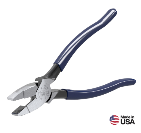](https://docs.retallickengineering.com/uploads/images/gallery/2026-04/image.png)
1x Ferrule Crimp (I cheat and use a more affordable Forged Wire Crimper, Klein Tools 2005N)
[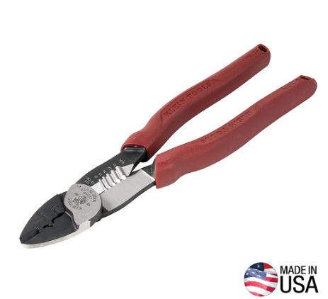](https://docs.retallickengineering.com/uploads/images/gallery/2026-04/Oqvimage.png)
| [](https://docs.retallickengineering.com/uploads/images/gallery/2026-04/signal-2026-04-08-171458.jpeg)
|
### **How to Build:**
Reading about this while at UnScruz or the Burn? Find DennisR/Overseer, I carry little kits with all the necessary components.
##### Step One: Gather Materials
Everything listed here is available at Home Depot for affordable prices. This is about a $20 project, including the adapter but without tools. $2.50 without. If you're just making one or two, I would avoid buying the Tools; Home Depot staff can cut the 28" steel wire for you from their "purchase per foot" spool. One of your friends will have a pair of wire strippers with a wire crimp in its handle, or check out your local library if they have a tool rental program. Oakland Library's loan tools; these tools are most likely in their inventory. Borrowing them saves you $70.
#####
Step Two: Secure the Adapter to the cable
Important: Do not pull the wire rope tight around the L5 adapter, as it will slowly chew away at the plastic cable shielding if it can't rotate. Leave enough extra wire in the loop for it to move freely around the L5 Adapter.
Slide the Ferrule down the wire and create a loop around the L5 Adapter, leaving about 3/4" excess through the Ferrule. Because the loop's radius is so small/tight, you will need to hold the wires/furrule in place to crimp it. Using my non-dominant hand, I pinch both wires
| Slide the Wires through the Ferrule and around the Adapter, being tight enough that it can't slide through, but loose enough that the adapter can move freely.
<IMAGE> | Using my non-dominant hand, I pinch both wires below the Ferrule to hold it in place.
<IMAGE>
| Using your Crimp tool, crimp 1/4th of the Ferrule on the edge. Once the first crimp is done you can let go of pinching the end and move the ferrule around as needed for effective crimping
<IMAGE> |
Note: If you're adding Heat Shrink \[Step Four\], add it to the cable now, don't heat it down till the end but add it before you create the second loop.
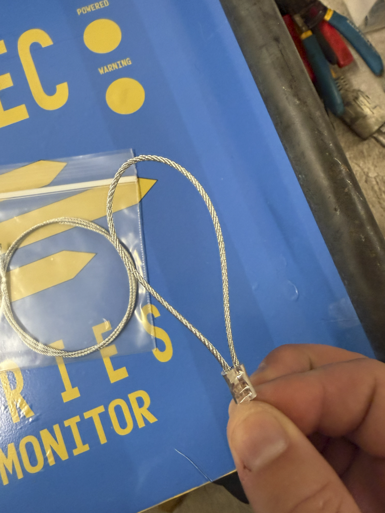
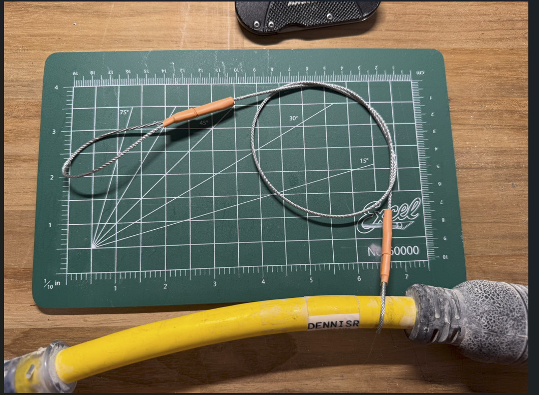
##### Step Three: Create the Locking Loop
Slide the Ferrule down the other side of the wire and create a loop just slightly bigger than the large end of the L5 Adapter, leaving about 3/4" excess through the Ferrule. Crimp the cable, and you're done!
| Slide the Wires through the Ferrule and around the Adapter, being tight enough that they can't slide through, but loose enough that the adapter can move freely.
<IMAGE> | Using my non-dominant hand, I pinch both wires below the Ferrule to hold it in place.
[](https://docs.retallickengineering.com/uploads/images/gallery/2026-04/zUBimage.png)
| Using your Crimp tool, crimp 1/4th of the Ferrule on the edge. Once the first crimp is done, you can let go of pinching the end and move the ferrule around as needed for effective crimping
<IMAGE> |
##### Step Four: Optional Features:
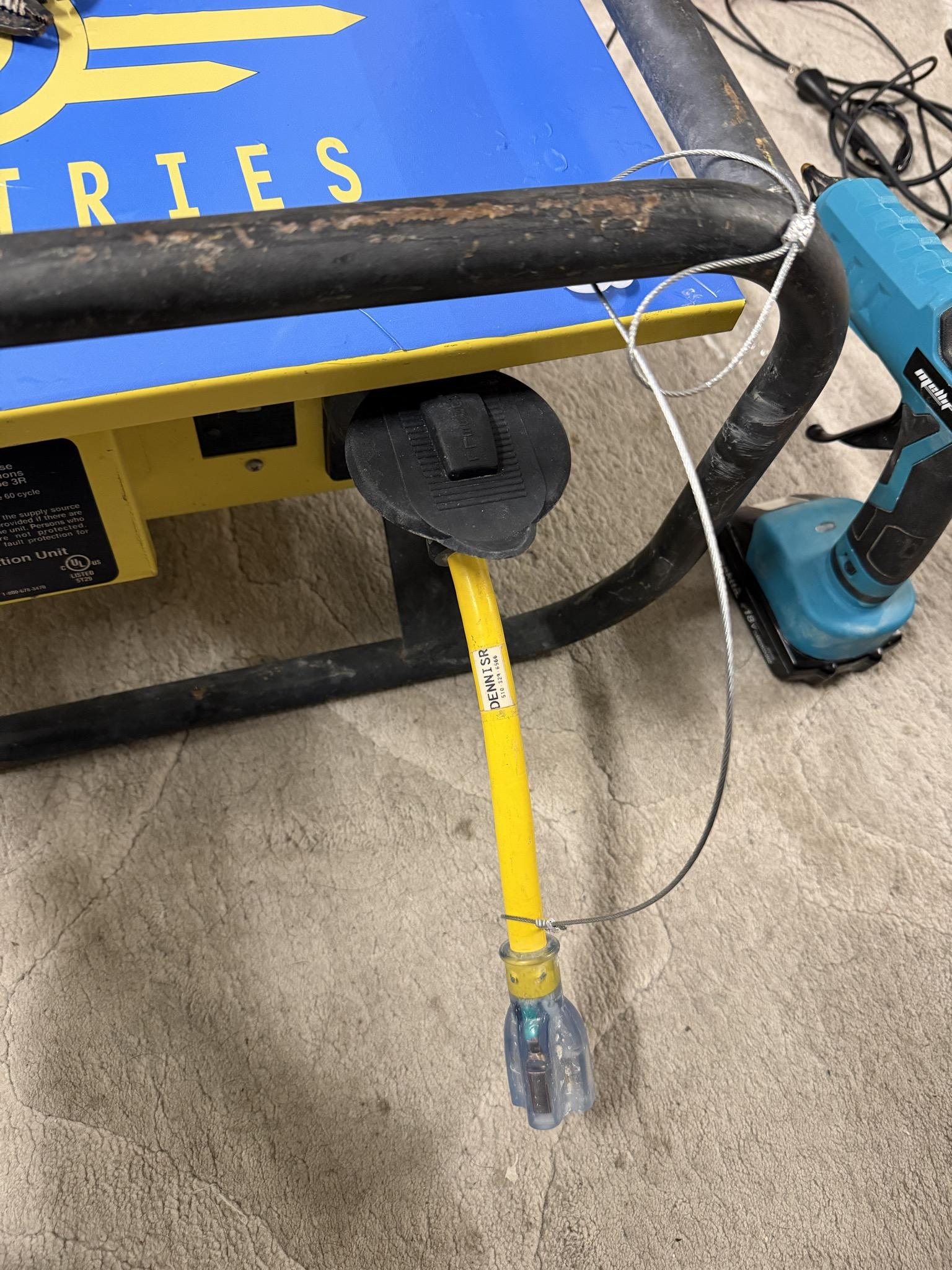
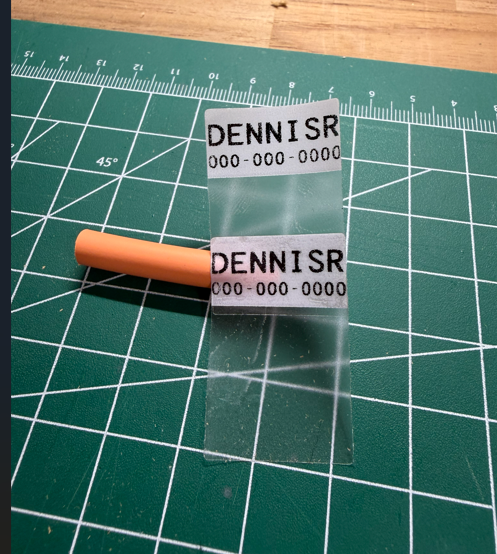
Add a Label with your contact info: I use 1.5x1" Self Laminating labels used for CatX cables. They have a small label, .75"x1", with a long clear laminating half of the sticker design to wrap around a smaller cable once or twice. I double them up, adding two labels so my contact info is on both sides. Keep it simple, I recommend just your First name, last initial, and your phone number. Mine says "DENNISR" with my number under the name, or "PLEASE RETURN" with my number under it.
| Connect the two Labels together.
[](https://docs.retallickengineering.com/uploads/images/gallery/2026-04/GjAimage.png)
| Please place the label side (top) down first on the adapter.
[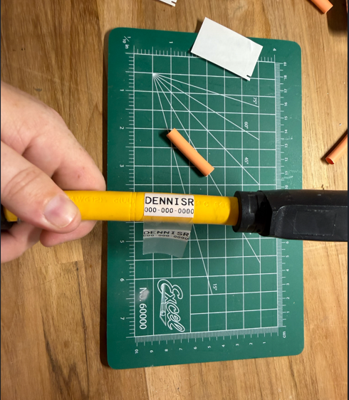](https://docs.retallickengineering.com/uploads/images/gallery/2026-04/Ebfimage.png)
| Wrap it around the cable, letting the extra clear vinyl wrap over the label.
[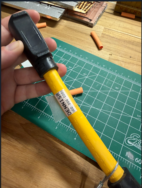](https://docs.retallickengineering.com/uploads/images/gallery/2026-04/O6Iimage.png)
|
Add heatshrink over the crimps: Over time, the tail ends sticking out of the crimped surface will fray. It's recommended to treat the ends, but since the 1/16th cable is so small, there aren't many options. Most of the time, I see a thick, most likely two-layer, heatshrink over the Ferrule and the extra tail of wire. If you have advice on this one, please let me know. I've also seen people add solder to the ends to prevent fraying and extend longevity.
[](https://docs.retallickengineering.com/uploads/images/gallery/2026-04/AsNimage.png)
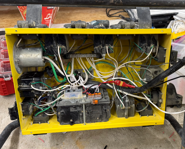
# Spider Box Projects: Shelly EM Remote Monitoring
### **Part Documented: Shelly EM Remote Monitoring**
Disclaimer: This requires modifying parts of the spiderbox's electrical system. Do not attempt without previous electrical knowledge and experience. Have an experienced electrician check your work.
This idea stems from a previous proposal to add monitoring to a larger 3-phase distribution unit for Burning Man. Shelly Modules are affordable, easy to install, and maintain.
####
#### **Materials Used:**
1x Shelly Gen3 EM 50a
1x Shelly 50a Current Transformer
10x Various Wago connectors \[2x and 3x\]
1x Spool of 12awg wire, two colors
#### **Tools Needed:**
1x Collection of various Electrical Tools including a pair of wire strippers
1x Hot glue gun with glue sticks
1x (optional) label maker
<Image of Tool>
Example:
1x Ferrule Crimp (I cheat and use a more affordable Forged Wire Crimper, Klein Tools 2005N)
[](https://docs.retallickengineering.com/uploads/images/gallery/2026-04/Oqvimage.png)
| [](https://docs.retallickengineering.com/uploads/images/gallery/2026-04/XTdimage.png)
[](https://docs.retallickengineering.com/uploads/images/gallery/2026-04/Molimage.png)
|
### **How to Build:**
**Besure to reference any warnings here**
##### Step One: Gather Materials
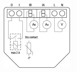
1. Shelly EM Gen3 50a -> Couple of core reasons for picking this product:
1. It matches the amperage rating of the spider box \[240 @ 50a\]
2. Can Monitor Two Phases
3. Stores up to 10 days of data logging locally onboard the device \[aka no server needed\]
4. Includes a dry contact for additional features
#####
Step Two: <Start the Build Guide>
<a description of the step of the process>
| Steps Should include Photos
<IMAGE> | And be broken up into no more then
<IMAGE>
| Three images and escriptions.
<IMAGE> |
##### EXAMPLE: Step Three: Create the Locking Loop
Slide the Ferrule down the other side of the wire and create a loop just slightly bigger than the large end of the L5 Adapter, leaving about 3/4" excess through the Ferrule. Crimp the cable, and you're done!
| Slide the Wires through the Ferrule and around the Adapter, being tight enough that they can't slide through, but loose enough that the adapter can move freely.
<IMAGE> | Using my non-dominant hand, I pinch both wires below the Ferrule to hold it in place.
<IMAGE>
| Using your Crimp tool, crimp 1/4th of the Ferrule on the edge. Once the first crimp is done, you can let go of pinching the end and move the ferrule around as needed for effective crimping
<IMAGE> |
##### Step Four: Optional Features:
List your optional Features: list one option part and its additional information here as the last step.
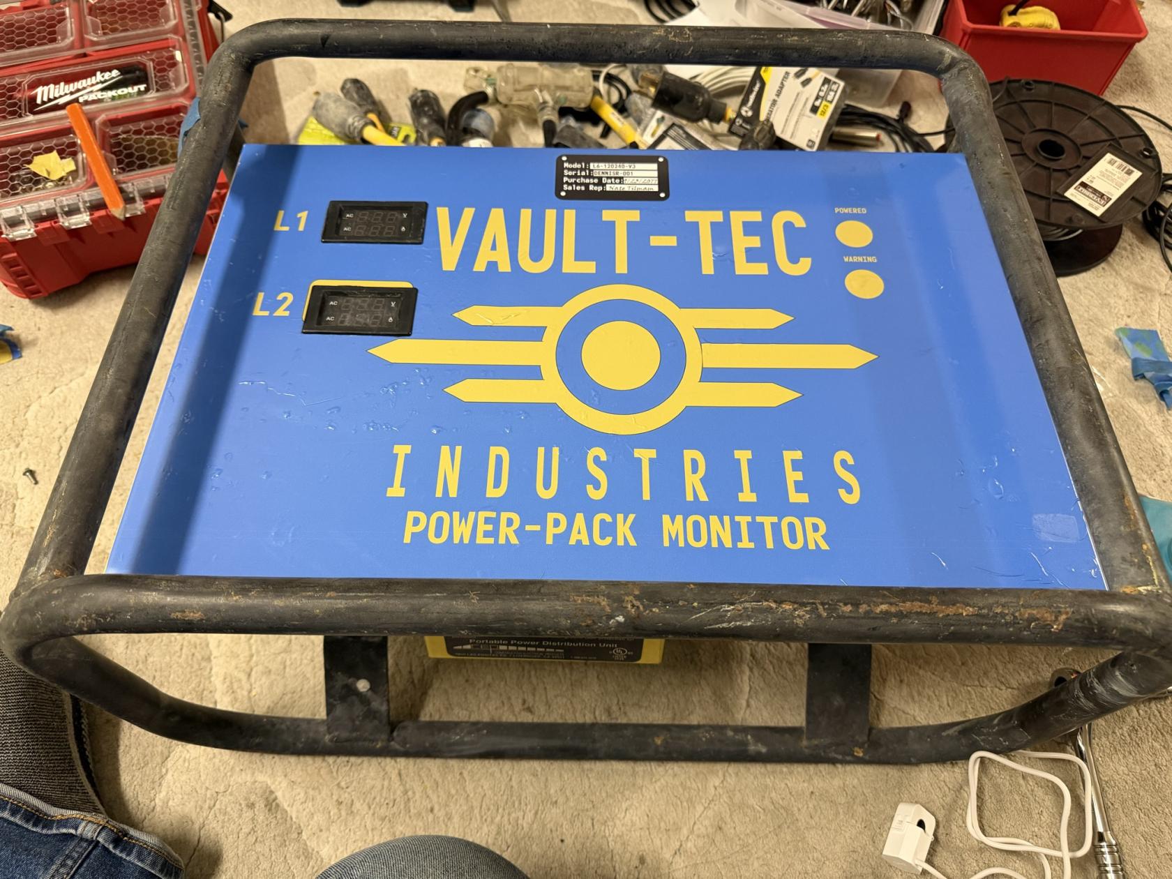
# Spider Box Projects: Vinyl Wrapping
### **Vinyl Wrapping**
| I've always wanted to paint my tow behind generator Blue with Vault-Tec branding. As I don't currently have a generator anymore, I thought I'd do my Spiderboxes. Having created the them camp Vault 21+ on Playa, it just made sense to keep the Fallout theme running.
#### **Materials Used:**
1x Vinyl Wrap, printed by my favorite shop, 11.5 x 22"
1x Various Heavy Duty cleaners and degreasers
#### **Tools Needed:**
Heat Gun - Bauer \[Harbor Freight\] carries one for $35. If you buy a $150 Milwuakee one, you'll waste $115... It's a heat gun. (Say's the guy with his $215 cordless Makita Heat gun)
[](https://docs.retallickengineering.com/uploads/images/gallery/2026-04/q9uimage.png)
| [](https://docs.retallickengineering.com/uploads/images/gallery/2026-04/img-1990.jpg)
Disclaimer: Vault-Tec is trademarked by ZeniMax Media Inc, the owners of Bethesda. This was done purely for fun; I have not, and will not, gain any profit from this. Please don't sue meeeee. Also, that is why the template used is not listed here for public download, and I will not be sharing it.
|
### **How to Build:**
##### Step One: Gather Materials
Don't use my design; be creative and create something unique to you! Create your own sticker with notes and warnings. I've always wanted to create a complete technical drawing of the electrical layout in the spider box for the cover plate.
The drawing was done in Adobe Illustrator with an art board of 11.5 x 22". The actual drawing has curved corners that I really liked, but to keep the cost down, \[about $15-20 a print!\]. it didn't go through a plotter, so all the cutting is on me to do at home.
[](https://docs.retallickengineering.com/uploads/images/gallery/2026-04/OuPimage.png)
I also made a pretend nameplate sticker as a part of the overall sticker. It might make more sense to make these as an alternative
sticker that you just add. I was being a little lazy and just added them to the main drawing instead of two pieces.
I like looking through Sci-Fi games or movies \[Especially 1970/1980s films: Alien / 5th Element\] like Avatar, Halo, Thunderbirds Are Go, Fallout, Starfield, and my friend Craig's Backyard for inspiration.
#####
Step Two: Send the drawing off to a print shop.
I highly recommend Silicon Valley Graphics. They have done most of my sticker printing since 2017. LoAnn and Usman are wonderful, quick to respond, and have a super quick turnaround time. Almost all of my orders have been processed the same day! Don't go to the big internet printers, go to your local and neighboring shop!
I always let them know when prints are for events like UnScruz or Burning Man, and they tend to give me a good price in exchange for agreeing to do some of the cutting myself or using scrap material. Happy to have been a customer of theirs for almost a decade.
[510-657-5853](tel:%20510-657-5853)
| **45333 Fremont Blvd. #5, Fremont, CA 94538** | [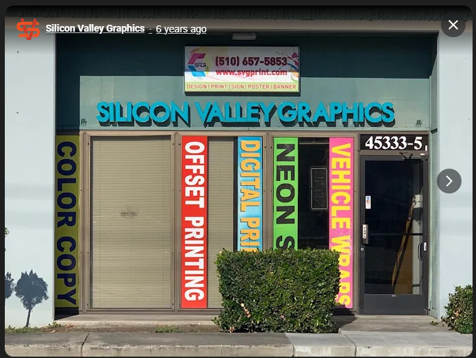](https://docs.retallickengineering.com/uploads/images/gallery/2026-04/IZBimage.png)
|
##### Step Three: Attaching the Vinyl.
This was really hard and required a lot of patience. The photos referenced in this document are my first attempt ever, and if you look closely, you can see the sticker covered in little dots. Those are air bubbles trapped under the vinyl. Hopefully, by the time you're reading this, I've replaced it with another attempt! Usman, with SVG, informed me that the bubbles are most likely from an uneven surface. While I did a deep clean of the surface before, I still rushed the process a little bit. It will take some experimenting to get it just right.
| Slide the Wires through the Ferrule and around the Adapter, being tight enough that they can't slide through, but loose enough that the adapter can move freely.
<IMAGE> | Using my non-dominant hand, I pinch both wires below the Ferrule to hold it in place.
<IMAGE>
| Using your Crimp tool, crimp 1/4th of the Ferrule on the edge. Once the first crimp is done, you can let go of pinching the end and move the ferrule around as needed for effective crimping
<IMAGE> |
##### Step Four: Optional Features:
List your optional Features: list one option part and its additional information here as the last step.