Labels and CAD Identifications
- Device, Cable, and Panel Labeling scheme.
- Device, Cable, and Panel Labeling scheme_old
- Badge Reader Install Notes
Device, Cable, and Panel Labeling scheme.
V2 of the Device, Cable, and Panel Labeling scheme. It keeps the V1 content and makes the formats consistent. Items marked PROPOSAL are new rules that need your decision. Items marked UNTESTED have not been checked on a real printer or site. Items marked FIELD are how I actually label on jobs (first example: 919 Stanford, October 2026). Where FIELD and a proposal disagree, FIELD wins.
Scope
How to name and label sites, rooms, panels, patch panels, devices, and cables in my installations. Based loosely on ANSI/TIA-606 (see "Relation to TIA-606" below). Device naming (firewalls, switches, cameras, access control) is my own convention, not part of 606.
General rules
| Rule | Detail |
|---|---|
| Characters | Uppercase letters, digits, - and .. No &, no /. Lowercase is used only for the suffix letter (see below). IDs have no spaces. FIELD: location lines on a label may use spaces (GARAGE RACK01). |
| Patch panel port | FIELD: P + panel number, dash, port. Example: P1-16 = patch panel 1, port 16. This dash is part of the port ID, not a field separator. |
- (dash) | Separates fields: site, then room or device, then patch panel or role. Example: SASC-IDF.1.01-P6-12 |
. (dot) | Separates numbers inside one field: floor, door or panel number, port. Example: IDF.1.01 = IDF, floor 1, door 01. SW01.49 = switch 01, port 49. |
| Suffix letter | Lowercase a, b, ... for a second item at the same spot, or the legs of a split cable. Example: SASC-IDF.1.01b, P6-12a. |
| Padding | PROPOSAL. Floor: 1 character. Door, panel, device number, port: 2 digits (01). Cable serial numbers: 3 digits (001). |
| Floors | PROPOSAL. 1 = ground or entry floor, 2, 3 ... above. B = basement (B, then C for a second basement level). |
| Site prefix | Required on room, panel, and device labels. May be left off cable labels when both ends are in the same site (saves label space). |
| Same label both ends | Every cable gets the same label at both ends. A cable label must use the exact device and port names on this page. |
Site codes
Short code per site: letters, or the street number for a building (919 = 919 Stanford). Fill in the table as sites are added.
| Code | Site | Notes |
|---|---|---|
919 | 919 Stanford | Multi-unit residential. See "Multi-unit residential" below. |
SASC | (fill in) | |
MHF | Wilson (fill in) | |
925 | (fill in) | Street number, like 919? |
Rooms, panels, and doors
Doors and panels are numbered clockwise, starting at the Main Entry. PROPOSAL: on other floors, start at the stair or elevator nearest the Main Entry.

| Type | Format | Example | Second one |
|---|---|---|---|
| Main Point of Entry (MPOE) | SITE-MPOE.floor.door | SASC-MPOE.1.06 | N/A. One MPOE per site. |
| Intermediate Distribution Frame (IDF) | SITE-IDF.floor.door | SASC-IDF.1.01 | SASC-IDF.1.01b (second IDF behind the same door) |
| Media cabinet / panel | SITE-PNL.floor.number | SASC-PNL.2.01 | SASC-PNL.2.02 |
| Facility door | SITE-DR.floor.door | SASC-DR.1.01 | SASC-DR.1.02 |
| Patch panel (inside a room or cabinet) | P + number, top to bottom | P6 | P7 |
| Patch panel port | P#-port | P6-12 | P6-12a, P6-12b (split cable) |
| Port, full name | SITE-ROOM-P#-port | SASC-IDF.1.01-P6-12 |
The patch panel face only needs the short form (P6-12), because the room is already known. Use the full name in records and on riser cables.
Notes
MPOE: where the carrier's service enters the building (the demarc). In houses it is often under the stairs or in the basement. In large buildings, riser cables run from the MPOE (or the main equipment room) up to the IDFs on other floors.
IDF: the room or rack on each floor that holds the switches for that floor. It connects back to the MPOE with riser cables.
Device labels
Network and server devices
| Type | Format | Example | Second one |
|---|---|---|---|
| ISP handoff (modem / ONT) | SITE-ISP## | MHF-ISP01 | MHF-ISP02. Put the carrier name (e.g. ATT) in the records, not the label. |
| Firewall / router | SITE-FW## | SASC-FW01 | SASC-FW02 (HA pair: 01 = primary) |
| Aggregation / distribution switch | SITE-AGG## | SASC-AGG01 | SASC-AGG02 |
| Access switch | SITE-SW## | SASC-SW01 | SASC-SW02 |
| Wireless access point | SITE-AP## | SASC-AP01 | PROPOSAL (new in V2) |
| Server / host | SITE-SRV## | SASC-SRV01 | PROPOSAL (new in V2) |
| NAS | SITE-NAS## | SASC-NAS01 | PROPOSAL (new in V2) |
| UPS / PDU | SITE-UPS##, SITE-PDU## | SASC-UPS01 | PROPOSAL (new in V2) |
Cameras
| Type | Format | Example | Second one |
|---|---|---|---|
| Internal camera | SITE-INT-What | SASC-INT-CashReg | SASC-INT-CashReg02 |
| External camera | SITE-EXT-What | SASC-EXT-DrivewayN | SASC-EXT-DrivewayS |
Cameras are named for what they look at. INT and EXT show access level at a glance: tenants and employees can usually see external cameras, but access to internal cameras is tightly controlled. The camera name is the exception to the uppercase rule, so it stays readable.
Access control (physical hardware in panels or on walls)
| Type | Format | Example | Second one |
|---|---|---|---|
| Door access hub | SITE-CTL.floor.door | SASC-CTL.1.05 | SASC-CTL.1.05b |
| Reader-Flex (no hub) | SITE-CTL.floor.door | SASC-CTL.1.01 | SASC-CTL.1.01b |
| Badge reader | (controller)-RDR | SASC-CTL.1.05-RDR | SASC-CTL.1.05-RDRb (second reader, e.g. exit side) |
| Door intercom | (controller)-INT | SASC-CTL.1.05-INT |
The door number in a CTL label is the same as in the door's own label (SASC-DR.1.05 uses SASC-CTL.1.05).
Cable labels
Every cable gets the same wrap label at both ends. Upstream (the end closer to the ISP / core) always comes before downstream.
Structured cable runs (in-wall: rack to unit, rack to outlet, riser)
FIELD. Three-line label:
| Line | Content | Example |
|---|---|---|
| 1 (large) | Cable ID = the patch panel port at the upstream end | P1-16 |
| 2 | Upstream location (room or rack) | GARAGE RACK01 |
| 3 | Downstream location (unit or room, and position) | APT-G.02 |
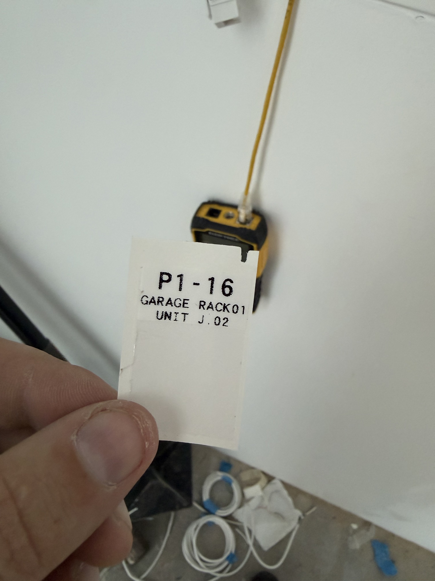
919 Stanford: the cable from garage rack 01, patch panel 1, port 16 to position 02 in the Apartment G media panel.
The bottom line of this label is wrong: it says UNIT J.02, but the cable goes to Apartment G. Use the layout, not the text. It should read APT-G.02.
Patch cords between devices
Two-line label. Line 1 = upstream device and port, line 2 = downstream device and port, using the device names on this page plus .port.

The diagram above is from V1 and may still show V1 formats.
This is different from TIA-606, where the near end is printed first so the order flips at each end. Here the order is always upstream first, so the label reads the same everywhere.
| Cable | Line 1 (upstream) | Line 2 (downstream) | Notes |
|---|---|---|---|
| ISP to firewall | ISP01 | FW01.WAN1 | Second WAN: ISP02 / FW01.WAN2 |
| Firewall to aggregation switch | FW01.03 | AGG01.01 | HA: FW02.03 / AGG02.01 |
| Aggregation to access switch | AGG01.10 | SW01.49 | Bond / LAG: label each member normally (e.g. AGG02.12 / SW01.49 and AGG02.13 / SW01.50). Record the LAG in the docs. |
| Switch to patch panel (patch cord in rack) | SW01.12 | P6-12 | |
| Patch panel to wall outlet (horizontal) | Three-line label: P6-12 / IDF.1.01 / FL1-WALL. The outlet faceplate shows P6-12. | Split cable: P6-12a, P6-12b | |
| Riser / backbone (between MPOE, IDFs, panels) | Three-line label: P1-01 / MPOE.1.06 / IDF.2.01 | Add the site prefix if the cable leaves the site. | |
| Building rack to unit media panel | FIELD. Three-line label: P1-16 / GARAGE RACK01 / APT-G.02 | See "Multi-unit residential". | |
| Camera | IDF.1.01-P3-05 or SW01.05 | INT-CashReg | The bottom line is the camera name. |
| Access hub to badge reader | CTL.1.05 | CTL.1.05-RDR | Intercom: CTL.1.05 / CTL.1.05-INT |
| Switch to access hub / Reader-Flex | SW01.20 | CTL.1.05 | |
FIELD: the 919 Stanford label fits one large line (P1-16) and two small lines of up to 13 characters (GARAGE RACK01) on the wrap label, with the clear tail left for laminating. Printed on the 1.5" x 1.0" M7-31-427 stock. Longer lines (more than 13 characters) are UNTESTED.
Service type (from V1)
V1 used a service prefix on patch cables: NET-001, TEL-001, COM-001. In V2 the panel port ID replaces the serial number. PROPOSAL: show the service with cable color (see Relation to TIA-606) or with a third line on the label. See Open questions.
Multi-unit residential
FIELD, from 919 Stanford. A building rack in the garage feeds a media panel (structured media enclosure) in each unit. The ISP's ONT sits in the unit media panel.
Names
| Item | Format | Example |
|---|---|---|
| Building rack | (ROOM) RACK## | GARAGE RACK01 |
| Patch panel port in the building rack | P#-port | P1-16 |
| Apartment (unit) | APT- + unit letter | APT-G |
| Position in the unit media panel | APT-(letter).##, counted left to right across the top row, then the next row | APT-G.02 |
| Room drop (unit panel to a room) | Letter = location, in order A, B, C .... Number = cable at that location: A1 is the first cable, A2 the second. | D1, A2 |
| ISP feed (single-mode fiber from the building rack to the unit ONT) | ISP-(apartment letter), location GARAGE | ISP-G |
| Tag on a cable inside the media panel | APT-(letter) (drop) | APT-G D1 |
| Drop location (small text under or over the ID) | FL#-MOUNT | FL1-WALL, FL2-CEILING, FL1-DRBL |
| Unused jack | BLANK | BLANK |
Unit media panel label strip
Each jack gets an ID (large) and a location (small). Jacks fed from the building rack use the rack port as the ID and GARAGE as the location. Red keystones mark the jacks fed from the garage rack.
| Row | 1 | 2 | 3 | 4 | 5 | 6 |
|---|---|---|---|---|---|---|
| Top | P1-15 GARAGE | P1-16 GARAGE | A1 FL1-DRBL | C1 FL2-WALL | E1 FL3-WALL | BLANK |
| Bottom | GARAGE ISP-G | BLANK | B1 FL1-WALL | D1 FL2-CEILING | BLANK | BLANK |
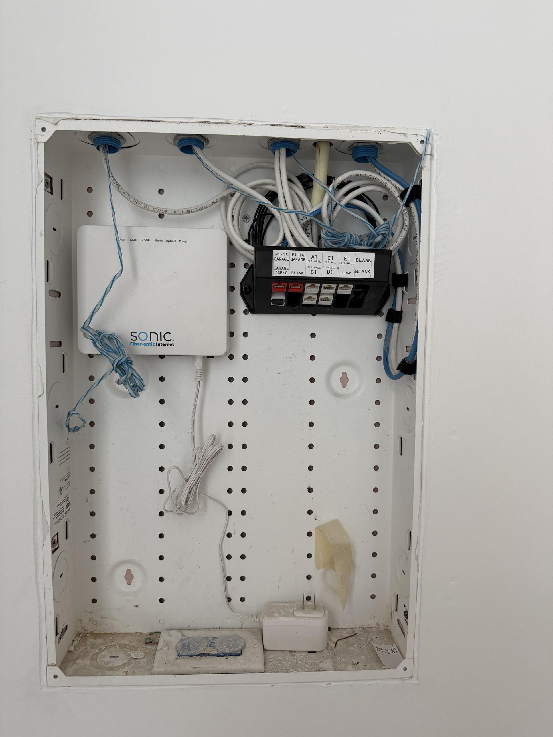
DRBL = doorbell. ISP-G = the ISP single-mode fiber for Apartment G, from the garage. Use APT- for units, not UNIT. Positions are counted across, so P1-16 is position .02 in the photo.
Stacking: put a second cable to the same location directly under the first (A1 on top, A2 below), so the cables for one location share a column. In the 919 Stanford photo each location has one cable, so A1/B1 and C1/D1 share columns.
Hardware and labels
Printer: Brady M710
| Label type | Size | Brady part number | Per roll | Price (V1, date unknown) | Ribbon |
|---|---|---|---|---|---|
| Basic sticker | 1.0" x 1.0" | M7-19-423 | 250 | $43.50 | (fill in) |
| Metallic label | 1.0" x 2.0" | M7-20-435 | 100 | $40.00 | (fill in) |
| Cable wrap (self-laminating) | 1.5" x 1.0" | M7-31-427 | 250 | $68.00 | R4300 ($73.00) |

Templates
Site template (editable): NetworkIdentification.docx
Patch bay label templates:
PatchBaySize_12portLevitonKeystone.docx
PatchBaySize_12portSurfacemount.docx
PatchBaySize_24portKeystone.docx
PatchBaySize_24port.docx
PatchBaySize_48port.docx
These templates were made for V1 formats and may need updating.
Relation to TIA-606
ANSI/TIA-606 is the US cabling administration standard. ISO/IEC 14763-2 is the international equivalent. This scheme borrows its ideas (unique IDs, both ends labeled, records kept) but uses its own formats.
| This scheme | TIA-606 term |
|---|---|
| MPOE | Entrance facility (demarc). Often in the same room as the equipment room / main cross-connect (MDF). |
| IDF | Telecommunications room (TR) |
| Riser cable | Backbone cable |
| Patch panel to outlet | Horizontal link |
| Multi-site with site codes | Class 3 (campus) / Class 4 (multi-site) |
606 color codes (from memory, not checked against the current revision)
| Color | Use |
|---|---|
| Orange | Demarc / carrier |
| Green | Network connections (customer side of demarc) |
| Purple | Common equipment (servers, PBX) |
| White | First-level backbone |
| Gray | Second-level backbone |
| Blue | Horizontal (to the outlet) |
| Brown | Between buildings |
| Yellow | Miscellaneous (security, alarms) |
| Red | Key telephone systems |
606-B cable example (kept from V1)
Near end AG09-35:01/AJ06-35:01, far end AJ06-35:01/AG09-35:01. AG09 = rack at grid AG09, -35 = patch panel 35 rack units from the bottom, :01 = port 1, / = separates near end from far end. Newer revisions (606-C, 606-D) exist. I have not checked what changed.
Changes from V1
| Item | V1 | V2 |
|---|---|---|
| MPOE | SASC-MPO.1.6 | SASC-MPOE.1.06 |
| IDF second unit | IDF-1-1a | SASC-IDF.1.01b |
| Doors | SASC-01-DR01 | SASC-DR.1.01 |
| Firewall on cables | FW-Primary-WAN1 | FW01.WAN1 (same name as the device label) |
| Aggregation switch | AGG-## and AGGR-## | AGG##, with its own device row |
| Site 925 devices | 925-FW01 | Same format, but see Open questions about the code |
| Wilson-MHF patch port | MHF-IDF2.1-P1.1 | MHF-IDF.2.01-P1-01 (same rule as every site) |
| Access hub suffix | 1.1A / 1.05a mixed | Always lowercase: 1.05b |
| Intercom / reader | -IntCom, -Reader | -INT, -RDR |
| Cameras | INTERNAL-CashReg | SASC-INT-CashReg |
| Camera cable | SASC-CAM-1.05 | Port ID / camera name |
| Wire label order | Two conflicting wordings | Upstream before downstream. In-wall runs: 3 lines (ID / upstream / downstream), from field practice. |
| Patch panel port | P6.12 | P6-12 (field practice) |
| Bond cables | -BONDa / -BONDb | Label each member normally. LAG in the records. |
| New | General rules, site code table, AP / SRV / NAS / UPS / PDU, patch panel naming, 606 mapping |
Open questions
- Fill in the site code table. Is
925a street number, like919? - Agree with the separator, padding, and floor proposals?
- Service type: drop
NET/TEL/COM, use cable color, or add a third label line? What didCOMmean? - Are MPOE and MDF always the same room in your sites, or do you need an
MDFroom type? - Do you want rack positions (rack units, as in 606) in the labels, or is
P#top to bottom enough? - Riser and outlet labels with lines longer than 13 characters still need a test print.
- Ribbon part numbers for the basic and metallic labels.
Related pages
- V1 of this page, saved as a copy ending in "_old" (link to be added)
Device, Cable, and Panel Labeling scheme_old
----
This is constantly changing as I try to document and standardize what I do in my installations.
Hardware and Labels used:
Printer: Brady M710 Label Maker:
Labels:
| Label Type | Label Size | Brady Part Numer [URL] | Count Per Roll | Estimate Price | Required Ribbon |
| Basic Sticker | 1.0" x 1.0" | M7-19-423 | 250 | $43.50 | |
| Metallic Label | 1.0" x 2.0" | 100 | $40.00 | ||
| Cable Wrap Sticker | 1.5" x 1.0" | 250 | $68.00 | R4300 - $73.00 |
Printable Site Template Guide:
Editable Document: NetworkIdentification.docx
Panels / Doors Labels:
All panels are counted clockwise from either MPOE or Main Entry.
Start at the Main Doorway and count clockwise around the Facility.
| Location/Type | First | Example | Expansion |
| Main Point of Entry | (Site)-MPOE.(Floor).(door) | SASC-MPO.1.6 | N/A - Only 1 MPOE per side |
| Intermediate Distribution Frame | (Site)-IDF.(Floor).(Door) | SASC-IDF.1.1 | IDF-1-1a, IDF-1-1b |
| Media Cabinets/Panels | (Site)-PNL.(Floor).(Panel Number) | SASC-PNL.1.1, SASC-PNL.2.1 | |
| Facility Doors: | (Site)-FL-DR## |
SASC-01-DR01 |
Notes:
MPOE - This is where the internet comes into the building. In residential buildings, it is commonly seen as a utility hidden under stairs or in basements. In large commercial buildings, it's widely known that risers [cables that link IDFs in other floors or wings] are used.
IDF - This is where your switching or server equipment is located to support each floor. This commonly hosts switches that connect back to the MPOE
Cable Labels:
606-B Notes:
Near end = AG09-35:01/AJ06-35:01
Far end = AJ06-35:01/AG09-35:01
If standing at rack location AG09, reading this near-end cable identifier will describe both the near-end and far-end locations.
AG09 = Rack or cabinet at grid location AG09 within the data center
-35 = Patch panel located 35 rack units from the bottom in rack AG09
:01 = Port 01 in patch panel located 35 rack units from the bottom of rack AG09
/ = Separator for near-end/far-end location description
AJ06 = Rack or cabinet at grid location AJ06 within the data center
-35 = Patch panel located 35 rack units from the bottom in rack AJ06
:01 = Port 01 in patch panel located 35 rack units from the bottom of the rack in AJ06
| Examples | First | Example | Expansion |
| SASC Patch Bay to Environment | (Panel Number).(Port Number on Panel) | P6.12 | P6.12a | P6.12b [only applies to split cables] |
| SASC to Device | (Panel Number).(Port Number on Panel) | P6.12 | P6.12a | P6.12b [only applies to split cables] |
| Wilson-MHF | (site)-(IDF#)-(Panel Number).Port Number | MHF-IDF2.1-P1.1 | N/A |
Device Labels:
Controllers: Physical hardware in Panels, Walls or mounted to walls
| Location/Type | First | Example | Expansion |
| Door Access Hub | (site)-CTL.(floor)-(door number) | SASC-CTL.1.05 | SASC-CTL.1.05a |
| Door Intercom | (Acesss Hub)-IntCom | SASC-CTL.1.05-IntCom | IntCom |
| Door Badge Reader | (Acesss Hub)-Reader | SASC-CTL.1.05-Reader |
Network Devices:
| Location/Type | First | Example | Expansion |
| Firewall/Router | (site)-FW## | 925-FW01 | 925-FW02 |
| Switches | (site)-SW## | 925-SW01 | 925-SW02 |
| Cameras | (location)-(object-in-camera) | INTERNAL-CashReg | INTERNAL-CashReg02 |
Notes:
Cameras have special naming schemes. We define them as internal or external to quickly identify access. Tenants and Employees typically can access external cameras, but internal camera access is heavily policed. A camera overlooking a driveway would be called "EXTERNAL-Driveway-North"
Patch Bay printed label templates:
PatchBaySize_12portLevitonKeystone.docx
PatchBaySize_12portSurfacemount.docx
PatchBaySize_24portKeystone.docx
PatchBaySize_48port.docx
PatchBaySize_24port.docx
Wire In between Devices:
2x Layer labels. Order of spanning tree. Top of label = First location. The bottom of the Label = end of the cable.
| Device | Fire | Example | Expansion/Options |
| Device |
Top: Where it terminates Bottom: What it terminates |
|
|
| ISP to Firewall/Router |
(site)-ISP.## [Number or name] FW-Primary-PORT |
MHF-ISP.001 FW-Primary-WAN1 |
ISP-AT&T FW-Secondary-WAN2 |
| Router to Distribution Switch |
FW/ROUT.Port AGGR-##.PORT |
FW-Primary.03 AGGR-01.01 |
FW-Secondary.03 AGGR-02.01 |
| Router/Agg to L3/2 Switch IN MPOE |
AGG-##.Port SW##.Port |
AGGR-01.10 SW01.49 |
AGGR-02.12-BONDa AGGR-02.13-BONDb |
| Patch Cables between IDF/MPOE and the environment |
(thing)-(floor)-(number) Service*-### *NET | *TEL | *COM | |
MHF-IDF.1.2 NET-001 *TEL-001 |
IDF-1-2 NET-001a |
|
Riser Cables [between MPOE, IDF, Panels] |
(site)-(thing).(floor).(number) (site)-(thing).(floor).(number) |
MHF-IDF.1.001 SASC-PNL.2.001 |
IDF-1-1.001a, IDF-1-1.001b PNL-1-2.002a |
| Badge Readers |
(site)-CTL.(floor).(number)-Reader |
SASC-CTL.1.05-Reader | |
| Camera Cable | (thing)-(floor)-(number) CAM-### |
SASC-CAM-1.05 |
|
| Access-Hub (not in panel) |
(site)-CTL.(floor)-(door number) |
SASC-CTL.1.1A | SASC-CTL.1.1B |
| Reader-Flex (no Hub) |
(site)-CTL.(floor)-(door number) |
SASC-CTL.1.1A | SASC-CTL.1.1B |
Badge Reader Install Notes
Badge Reader Heights:
Note: Assume all measurements are to the "Center point" of object
| Location - Customer | Interior Heights | Exterior Heights | Distance in from the doorjam | Special Notes | Paint/Color used |
| SASC | 46" from Ground to Badge reader | 47" from ground to center of badge reader. | Exterior: 7.5" from door jam, handle side | + or - 2", varies based on if a light switch is in proximity of badge reader: Adjust to match switch center line | External Boxes: BEHR Chiffon Cream MATTE |
| Wilson's | ADA Compliance is a must with Wilson Properties. |
ADA Compliance
Legal Expectations: No lower than 36" and no higher than 48"
DOJ CFR Part 36 Official Notes:
Height and Reach Requirements
ADA has certain height and reach requirements to allow access for customers in wheelchairs. As these height and
reach limitations may cause the weather overhang on keypads to obstruct the vision of taller customers, PTI sells a
housing for keypads that does not have a weather overhang. APEX keypads may also be flush-mounted in a wall to
prevent this issue. Either of these items may be purchased from PTI.
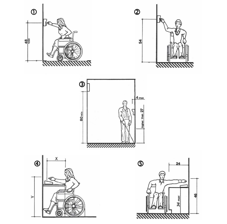
- Keypads should be mounted so that the top of the number touchpad is no more than 48” above the finished
floor with no obstructions in locations where wheelchair access is available only from the front. See Figure 1. - Keypads should be mounted so that the top of the number touchpad is no more than 54” above the finished
floor with no obstructions in locations where the wheelchair has sideways access. See Figure 2. - Keypads should not be mounted so as to protrude more than 4” from the wall. If mounted in a bollard or
pylon, it may protrude up to 12”. Multiplexers and other items mounted higher on the wall or ceiling must be
80” or higher above the finished floor. See Figure 3. - Falcon Base Units and computers should be placed on desks that meet ADA requirements between 28” –
34” tall with no more than 20” in reach depth for obstructed front access or 24” in reach depth for obstructed
side reach access. See Figures 4 & 5. In Figure 4, if X < 20” then Y = 48”. When X = 20” to 25”, then Y =
44”. X should always be ≤ 25”.
Visual CAD: